|
LECTURE -1 INTRODUCTION,COMPONENTS & DATA
REPRESENTATION Data
Communications:(RGPV DEC-2013) The term telecommunication means
communication at a distance. The word data refers to information presented in
whatever form is agreed upon by the parties creating and using the data. Data
communications are the exchange of data between two devices via some form of
transmission medium such as a wire cable. Data Communication is a process of
exchanging data or information ·
In case of computer networks this
exchange is done between two devices over a transmission medium. ·
This process involves a communication
system which is made up of hardware and software. ·
The hardware part involves the sender
and receiver devices and the intermediate devices through which the data
passes. ·
The software part involves certain
rules which specify what is to be communicated, how it is to be communicated
and when. It is also called as a Protocol. Characteristics of Data Communication The effectiveness of any data communications system
depends upon the following four fundamental characteristics: 1.
Delivery: The data
should be delivered to the correct destination and correct user. 2.
Accuracy: The
communication system should deliver the data accurately, without introducing
any errors. The data may get corrupted during transmission affecting the
accuracy of the delivered data. 3.
Timeliness:
Audio and Video data has to be delivered in a timely manner without any
delay; such a data delivery is called real time transmission of data. 4.
Jitter: It is the
variation in the packet arrival time. Uneven Jitter may affect the timeliness
of data being transmitted. Components of Data Communication: A Data Communication system has five components as
shown in the diagram below
Fig. Components of a Data Communication
System |
||||||||
|
1. Message :-Message
is the information to be communicated by the sender to the receiver. 2. Sender :-The
sender is any device that is capable of sending the data (message). 3. Receiver :-The receiver is a device
that the sender wants to communicate the data (message). 4. Transmission Medium :-It is the
path by which the message travels from sender to receiver. It can be wired or
wireless and many subtypes in both. 5. Protocol :-It is an agreed upon set or
rules used by the sender and receiver to communicate data. A protocol is
a set of rules that governs data communication. A Protocol is a necessity in data communications without which
the communicating entities are like two persons trying to talk to each other
in a different language without know the other language DATA REPRESENTATION Data is collection of raw facts which is processed to deduce
information. There may be different forms in which data may be represented.
Some of the forms of data used in communications are as follows: 1. Text Text includes
combination of alphabets in small case as well as upper case. It is stored as a pattern of bits. Prevalent encoding system :
ASCII, Unicode 2. Numbers Numbers
include combination of digits from 0 to 9. It is stored as a pattern of bits. Prevalent encoding system :
ASCII, Unicode 3. Images An image is worth a thousand words‖ is a very famous
saying. In computers images are digitally stored. A Pixel is the smallest
element of an image. To put it in simple terms, a picture or image is a
matrix of pixel elements. The pixels are represented in the form of bits.
Depending upon the type of image (black n white or color) each pixel would
require different number of bits to represent the value of a pixel. The size
of an image depends upon the number of pixels (also called resolution) and
the bit pattern used to indicate the value of each pixel. Example: if
an image is purely black and white (two color) each pixel can be represented
by a value either 0 or 1, so an image made up of 10 x 10 pixel elements would
require only 100 bits in memory to be stored. On the other hand an image that includes gray may require 2 bits
to represent every pixel value (00 - black, 01 – dark gray, 10 -light gray,
11 –white). So the same 10 x 10 pixel image would now require 200 bits of
memory to be stored. Commonly used Image formats : jpg, png, bmp, etc 4. Audio Data can also
be in the form of sound which can be recorded and broadcasted. Example: What
we hear on the radio is a source of data or information. Audio data is continuous, not discrete. 5. Video Video refers to broadcasting of data in form of picture or movie
Ref: 1. Data Communication
and networking Behrouz a Forouzan 4th edition 2. http://npteldownloads.iitm.ac.in/downloads_mp4/106105082/lec01.mp4 |
||||||||
|
LECTURE -2 Data Representation:- Unipolar, Polar
& Bipolar (RGPV JUNE-2011) Digital Data to Digital Signal Coding methods Coding
methods are used to convert digital data into digital signals. There are two
types of coding methods: 1 Line Coding
2 Block Coding Scrambling is
also one of the ways to convert digital data to digital signals but is not
used. Line Encoding It is the process of converting Digital data into
digital signal. In other words, it is converting of binary data(i.e. A
sequence of bits) into digital signal (i.e. a sequence of discrete,
discontinuous voltage pulses)
Classification
of Line Codes The
following figure shows the classification of Line coding schemes: Figure : Classification of line coding schemes |
||||||||
|
A Unipolar All signal
levels are either above or below the time axis. NRZ - Non Return to Zero scheme is an example of this code. The
signal level does not return to zero during a symbol transmission. B Polar NRZ-voltages are
on both sides of the time axis. Polar NRZ scheme can be implemented with two voltages. E.g. +V
for 1 and -V for 0. There are two variations: o NZR - Level (NRZ-L) - positive
voltage for one symbol and negative for the other o NRZ - Inversion (NRZ-I) - the
change or lack of change in polarity determines the value of a symbol. E.g. a
―1‖ symbol inverts the polarity a ―0‖ does not. Polar – RZ The Return to Zero (RZ) scheme uses
three voltage values. +, 0, -. Each symbol has a transition in the middle. Either from high to
zero or from low to zero More complex as it uses three voltage
level. It has no error detection capability Figure : Unipolar(NRZ) & Polar(RZ & NRZ)
Encoding |
||||||||
|
Polar - Biphase: Manchester and Differential Manchester Manchester coding is a
combination of NRZ-L and RZ schemes. Every symbol
has a level transition in the middle: from high to low or low to high. It uses only two voltage levels. Differential
Manchester coding consists of combining the NRZ-I and
RZ schemes. Every symbol has a level transition in the middle. But the level
at the beginning of the symbol is determined by the symbol value. One symbol
causes a level change the other does not.
Figure
: Polar biphase: Manchester and differential Manchester coding schemes C Bipolar - AMI and Pseudoternary This coding scheme uses 3 voltage levels: - +, 0, -, to
represent the symbols Voltage level for one symbol is at ―0‖ and the other
alternates between + & -. Bipolar Alternate Mark Inversion (AMI) -
the ―0‖ symbol is represented by zero voltage and the
―1‖ symbol alternates between +V and -V. Pseudoternary is the
reverse of AMI Figure: Bipolar coding scheme - AMI and
Pseudoternary |


|
Ref:
1. Data Communication and networking Behrouz a Forouzan 4th edition 2. http://npteldownloads.iitm.ac.in/downloads_mp4/106105082/lec01.mp4
|

|
LECTURE -3 DATA
FLOW The devices communicate
with each other by sending and receiving data. The data can flow between the
two devices in the following ways. 1. Simplex 2. Half Duplex 3. Full Duplex Simplex
In Simplex,
communication is unidirectional Only
one of the devices sends the data and the other one only receives the data. Example: in the above diagram: a CPU send data while a monitor
only receives data Half
Duplex
In half
duplex both the stations can transmit as well as receive but not at the same
time. When one
device is sending other can only receive and vice-versa (as shown in figure
above.) Example: A walkie-talkie |
|
Full
Duplex
In Full
duplex mode, both stations can transmit and receive at the same time. Example: mobile phones Ref: 1. Data Communication and networking Behrouz a Forouzan 4th
edition 2. http://npteldownloads.iitm.ac.in/downloads_mp4/106105082/lec01.mp4 |


|
UNIT-I
DATA COMMUNICATION
LECTURE -4 |
||||||||||||
2. Serial Transmission (RGPV/
Dec.2012)
When transferring data between two
physically separate devices, especially if the separation is more than a few
kilometers, for reasons of cost, it is more economical to use a single pair
of lines. Data is transmitted as a single bit at a time using a fixed time
interval for each bit. This mode of transmission is known as bit-serial transmission. • In serial transmission, the various
bits of data are transmitted serially one after the other. • It requires only one communication
line rather than n lines to transmit
data from sender to receiver. • Thus all the bits of data are
transmitted on single line in serial fashion. • In serial transmission, only single
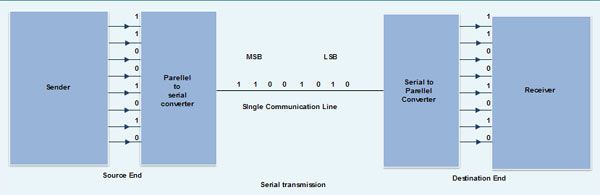
bit is sent with each clock pulse. • As shown in fig., suppose an 8-bit
data 11001010 is to be sent from source to destination. Then least
significant bit (LSB) i,e. 0
will be transmitted first followed by other bits. The most significant bit
(MSB) i.e. 1 will be
transmitted in the end via single communication line. • The internal circuitry of computer
transmits data in parallel fashion. So in order to change this parallel data
into serial data, conversion devices are used. • These conversion devices convert the
parallel data into serial data at the sender side so that it can be
transmitted over single line. • On receiver side, serial data received
is again converted to parallel form so that the interval circuitry of
computer can accept it
• Serial
transmission is used for long distance communication. Advantage of Serial
transmission
Use of single
communication line reduces the transmission line cost by the factor of n as compared to parallel
transmission. Disadvantages of Serial
transmission
1. Use of
conversion devices at source and destination end may lead to increase in
overall transmission cost. 2. This method is
slower as compared to parallel transmission as bits are transmitted serially
one after the other. Types of Serial Transmission
There are two types
of serial transmission-synchronous and asynchronous both these transmissions
use 'Bit synchronization' Bit Synchronization is a function that
is required to determine when the beginning and end of the data transmission
occurs. Bit synchronization helps the
receiving computer to know when data begin and end during a transmission.
Therefore bit synchronization provides timing control. Asynchronous Transmission (RGPV/Dec.2013)
• Asynchronous
transmission sends only one character at a time where a character is either a
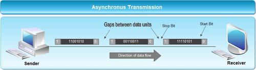
letter of the alphabet or number or control character i.e. it sends one byte of data at a time. • Bit
synchronization between two devices is made possible using start bit and stop
bit. • Start bit
indicates the beginning of data i.e.
alerts the receiver to the arrival of new group of bits. A start bit
usually 0 is added to the beginning of each byte. • Stop bit
indicates the end of data i.e. to
let the receiver know that byte is finished, one or more additional bits are
appended to the end of the byte. These bits, usually 1s are called stop bits.
• Addition of start and stop increase
the number of data bits. Hence more bandwidth is consumed in asynchronous
transmission. • There is idle time between the
transmissions of different data bytes. This idle time is also known as Gap • The gap or idle
time can be of varying intervals. This mechanism is called Asynchronous,
because at byte level sender and receiver need not to be synchronized. But
within each byte, receiver must be synchronized with the incoming bit stream. Application of Asynchronous
Transmission
1. Asynchronous
transmission is well suited for keyboard type-terminals and paper tape devices.
The advantage of this method is that it does not require any local storage at
the terminal or the computer as transmission takes place character by
character.
2. Asynchronous
transmission is best suited to Internet traffic in which information is
transmitted in short bursts. This type of transmission is used by modems. Advantages of Asynchronous
transmission
1. This method of
data transmission is cheaper in cost as compared to synchronous e.g. If lines are short,
asynchronous transmission is better, because line cost would be low and idle
time will not be expensive. 2. In this approach
each individual character is complete in itself, therefore if character is
corrupted during transmission, its successor and predecessor character will
not be affected. 3. It is possible
to transmit signals from sources having different bit rates. 4. The transmission
can start as soon as data byte to be transmitted becomes available. 5. Moreover, this
mode of data transmission in easy to implement. Disadvantages of asynchronous
transmission
1. This method is
less efficient and slower than synchronous transmission due to the overhead
of extra bits and insertion of gaps into bit stream. 2. Successful
transmission inevitably depends on the recognition of the start bits. These
bits can be missed or corrupted.
Ref:
1. Data Communication and networking Behrouz a Forouzan 4th edition 2. http://npteldownloads.iitm.ac.in/downloads_mp4/106105082/lec01.mp4
|


|
LECTURE -5 TRANSMISSION MODES(RGPV
DEC-2012) ·
Data is transmitted between two
digital devices on the network in the form of bits. ·
Transmission mode refers to the mode
used for transmitting the data. The transmission medium may be capable of
sending only a single bit in unit time or multiple bits in unit time. ·
When a single bit is transmitted in
unit time the transmission mode used is Serial Transmission and when multiple
bits are sent in unit time the transmission mode used is called Parallel
transmission. Types of Transmission
Modes There are two basic types of transmission modes Serial and
Parallel as shown in the figure below. Serial transmission is further categorized into Synchronous and
Asynchronous Serial transmission
FIG:-Types of Transmission Modes Parallel Transmission ·
It involves simultaneous transmission
of N bits over N different channels ·
Parallel Transmission increases
transmission speed by a factor of N over serial transmission ·
Disadvantage of parallel transmission
is the cost involved, N channels have to be used, hence, it can be used for
short distance communication only |
||||||||||||||||||||||||||||
|
Fig. Parallel Transmission of Data over N = 8
channels Example of Parallel Transmission is the communication between
CPU and the Projector. Serial Transmission In Serial
Transmission, as the name suggests data is transmitted serially, i.e. bit by
bit, one bit at a time. Since only one bit has to be sent in unit time only a single
channel is required.
Fig. Serial Transmission of Data over N = 8 channels Types of Serial Transmission: Depending upon the timing of transmission
of data there are two types of serial transmission as described below |
||||||||||||||||||||||||||||
|
Asynchronous Transmission ·
In asynchronous serial transmission
the sender and receiver are not synchronized. ·
The data is sent in group of 8 bits
i.e. in bytes. ·
The sender can start data
transmission at any time instant without informing the receiver. ·
To avoid confusing the receiver while
receiving the data, ―start‖ and ―stop‖ bits are inserted
before and after every group of 8 bits as shown below
Fig: Start and Bit before and after every data byte The start bit
is indicated by ―0 and stop bit is indicated by ―1 The sender
and receiver may not be synchronized as seen above but at the bit level they
have to be synchronized i.e. the duration of one bit needs to be same for
both sender and receiver for accurate data transmission. There may be
gaps in between the data transmission indication that there is no data being
transmitted from sender. Ex. Assume a user typing at uneven speeds, at times
there is no data being transmitted from Keyboard to the CPU. Following is the Diagram for Asynchronous Serial Transmission.
Fig: Asynchronous Serial Transmission |
||||||||||||||||||||||||||||
|
Advantages 1. Cheap and Effective implementation 2. Can be used for low
speed communication Disadvantages Insertion of start bits, stop bits and gaps make asynchronous
transmission slow. Application Keyboard Synchronous Transmission ·
In Synchronous Serial Transmission,
the sender and receiver are highly synchronized. ·
No start, stop bits are used. ·
Instead a common master clock is used
for reference. ·
The sender simply send stream of data
bits in group of 8 bits to the receiver without any start or stop bit. ·
It is the responsibility of the
receiver to regroup the bits into units of 8 bits once they are received. ·
When no data is being transmitted a
sequence of 0‘s and 1‘s indicating IDLE is put on the transmission medium by
the sender. Fig:
Synchronous Serial Transmission Advantage 1. There are
no start bits, stop bits or gaps between data units 2. Since the
above are absent data transmission is faster. 3. Due to synchronization there are no timing errors. |
||||||||||||||||||||||||||||
|
Comparison
of serial and parallel transmission
Ref: 1. Data Communication and networking Behrouz a Forouzan 4th
edition 2. http://npteldownloads.iitm.ac.in/downloads_mp4/106105082/lec01.mp4
|
||||||||||||||||||||||||||||
|
LECTURE -6 Encoding:
Unipolar Unipolar
encoding is a line
code. A positive voltage represents a binary 1, and zero volts indicates a binary 0. It is the simplest line code,
directly encoding the bitstream, and is analogous to on-off
keying in modulation. Its drawbacks are that it
is not self-clocking and it has a significant DC
component, which can be halved by
using return-to-zero, where the signal returns to zero in the
middle of the bit period. With a 50% duty
cycle each rectangular pulse is only at a
positive voltage for half of the bit period. This is ideal if one symbol is sent much
more often than the other and power considerations are necessary, and also
makes the signal self-clocking. NRZ(Non-Return-Zero)
(RGPV/
Dec 2012) Traditionally, a unipolar
scheme was designed as a non-return-to-zero (NRZ) scheme, in which the
positive voltage defines bit 1 and the zero voltage defines bit 0. It
is called NRZ because the signal does not return to zero at the middle of the
bit. Compared with its polar
counterpart, Polar NRZ, this scheme is very expensive. The normalized power
(power required to send 1 bit per unit line resistance) is double that for polar
NRZ. For this reason, this scheme is not normally used in data
communications today. Return
to zero codes (RGPV/ Dec
2012) Return-to-zero (RZ) describes a line
code used in telecommunications signals in which the signal drops (returns) to zero
between each pulse. This takes place even if a number of consecutive 0s or 1s occur in
the signal. The signal is self-clocking. This means that a separate clock does not
need to be sent alongside the signal, but suffers from using twice the
bandwidth to achieve the same data-rate as compared
to non-return-to-zero format. The "zero"
between each bit is a neutral or rest condition, such as a zero amplitude in pulse amplitude modulation (PAM), zero phase
shift in phase-shift keying (PSK), or mid-frequency in frequency-shift keying (FSK). That "zero" condition is
typically halfway between the significant condition representing a 1 bit and the other
significant condition representing a 0 bit. Although return-to-zero
(RZ) contains a provision for synchronization, it still has a DC component resulting in “baseline wander” during long
strings of 0 or 1 bits, just like the line code non-return-to-zero. Bipolar
Line Encoding In telecommunication, bipolar encoding is a type of line code, where
two nonzero values are used, so that the three values are +,-, and zero. Such
a signal is called a duobinary signal.
Bipolar encoding typically has at least a rough a balance of +'s and -'s.
One kind of bipolar
encoding is a paired disparity code. The
simplest example of this is alternate
mark inversion. In this code, a binary 0 is encoded as zero volts,
as in unipolar encoding, whereas a binary
1 is encoded alternately as a positive voltage or a negative voltage. The
name arose because, in the context of a T-carrier, a
binary '1' is referred to as a "mark", while a binary '0' is called
a "space". |
||||||||||||||||||||||||||||
|
Ref: 1. Data Communication and networking Behrouz a Forouzan 4th
edition 2. http://npteldownloads.iitm.ac.in/downloads_mp4/106105082/lec01.mp4
|


|
LECTURE -7 Line Codes (RGPV Dec 2011 / june 2013) In base band transmission best way is to
map digits or symbols into pulse waveform. This waveform is generally termed as Line
codes. RZ: Return to Zero [ pulse for half the
duration of Tb ] NRZ
Return to Zero[ pulse for full duration of Tb ]
Unipolar NRZ “1” maps to +A pulse “0” maps to no pulse Poor timing Low-frequency content Simple Long strings of 1s and 0s
,synchronization problem Polar
- (NRZ)
“1” maps to +A pulse “0” to –A pulse Better Average Power simple to implement Long strings of 1s and 0s
,synchronization problem Poor timing Bipolar
Code
Three
signal levels: {-A, 0, +A} • “1” maps to +A or –A in alternation • “0” maps to no pulse • Long string of 0’s causes receiver to loose
synchronization •
Suitable for telephone systems.
• “1” maps into A/2 first for Tb/2, and
-A/2 for next Tb/2 • “0” maps into -A/2 first for Tb/2, and
A/2 for Tb/2 • Every interval has transition in middle – Timing recovery easy • Simple to implement • Suitable for satellite telemetry and
optical communications Differential encoding t starts with one initial bit .Assume 0
or 1. Signal transitions are used for encoding. Example NRZ - S and NRZ – M NRZ –S : symbol 1 by no transition ,
Symbol 0 by transition. NRZ-M : symbol 0 by no transition ,
Symbol 1 by transition Suitable
for Magnetic recording systems. Voltage Build-up The use
of a bipolar code prevents a significant build-up of DC, as the positive and negative pulses
average to zero volts. Little or no DC-component is
considered an advantage because the cable may then be used for longer
distances and to carry power for intermediate equipment such as line
repeaters.The DC-component can be easily and cheaply removed before the
signal reaches the decoding circuitry. Synchronization and Zeroes
Bipolar encoding is preferable to non-return-to-zero whenever signal transitions are required
to maintain synchronization between the transmitter and receiver. Other
systems must synchronize using some form of out-of-band communication, or add
frame synchronization sequences that don't carry data to the
signal. These alternative approaches require either an additional
transmission medium for the clock signal or a loss of performance due to
overhead, respectively. A bipolar encoding is an often good compromise: runs
of ones will not cause a lack of transitions. However, long sequences
of zeroes remain an issue. Long sequences of zero bits result in no transitions and a loss of synchronization. Where
frequent transitions are a requirement, a self-clocking encoding such as return-to-zero or some other more complicated line
code may be more appropriate, though they
introduce significant overhead. The coding was used
extensively in first-generation PCM networks, and is still commonly seen on older multiplexing equipment today, but successful
transmission relies on no long runs of zeroes being present. No more than 15
consecutive zeros should ever be sent to ensure synchronization. There are two popular
ways to ensure that no more than 15 consecutive zeros
are ever sent: robbed-bit signaling and bit
stuffing. T-carrier uses robbed-bit
signaling: the least-significant bit of the byte is simply forced to a
"1" when necessary. The modification of bit 7
causes a change to voice that is undetectable by the human ear, but it is an
unacceptable corruption of a data stream. Data channels
are required to use some other form of pulse-stuffing,such as always setting
bit 8 to '1', in order to maintain a sufficient density of ones. If the
characteristics of the input data do not follow the pattern that every
eighth bit is '1', the coder using alternate mark inversion adds a '1' after
seven consecutive zeros to maintain synchronisation. On the decoder side,
this extra '1' added by the coder is removed, recreating the correct data.
Using this method the data sent between the coder and the decoder is longer
than the original data by less than 1% on average. Of course, this lowers the
effective data throughput to 56 kbit/s per channel. Ref:
1. Data Communication and networking Behrouz a Forouzan 4th edition 2. http://npteldownloads.iitm.ac.in/downloads_mp4/106105082/lec01.mp4 |
|||
|
S.NO |
RGPV QUESTIONS |
Year |
Marks |
|
Q.1 |
Explain
the line codes |
June2013 Dec 2011 |
7 7 |


|
LECTURE -8 Block
Coding (RGPV DEC-2013) Block
coding adds redundancy to line coding so that error detection can be
implemented. Block
coding changes a block of m bits
into a block of n bits, where
n is larger than m. Block
coding is referred to as an mB/nB encoding
technique. The
additional bits added to the original ―m bits‖ are called parity bits
or check bits
Ref:
1. Data Communication and networking Behrouz a Forouzan 4th edition 2. http://npteldownloads.iitm.ac.in/downloads_mp4/106105082/lec01.mp4
|
||||||||
|
LECTURE -9 Data
Compression(RGPV-DEC 2013)
Lossless Compression Methods — In lossless methods, original
data and the data after compression and decompression are exactly the same. — Redundant data is removed in
compression and added during decompression. — Lossless methods are used
when we can’t afford to lose any data: legal and medical documents, computer
programs. Run-length encoding — Simplest method of
compression. — How: replace consecutive
repeating occurrences of a symbol by 1 occurrence of the symbol itself, then
followed by the number of occurrences. The method can be more efficient if the data uses only 2 symbols (0s
and 1s) in bit patterns and 1 symbol is more frequent than another.
Huffman Coding — Assign fewer bits to symbols
that occur more frequently and more bits to symbols appear less often. — There’s no unique Huffman
code and every Huffman code has the same average code length. — Algorithm: ①
Make a leaf node for each code symbol
②
Take the two leaf nodes with the smallest probability and connect them
into a new node
③
If there is only one node left, the code construction is completed. If
not, go back to (2)
Lossy Compression Methods — Used for compressing images
and video files (our eyes cannot distinguish subtle changes, so lossy data is
acceptable). — These methods are cheaper,
less time and space. — Several methods: § JPEG: compress pictures and
graphics § MPEG: compress video § MP3: compress audio JPEG Encoding — Used to compress pictures
and graphics. — In JPEG, a grayscale picture
is divided into 8x8 pixel blocks to decrease the number of calculations. — Basic idea: § Change the picture into a
linear (vector) sets of numbers that reveals the redundancies. § The redundancies is then
removed by one of lossless compression methods.
MPEG Encoding — Used to compress video. — Basic idea: § Each video is a rapid
sequence of a set of frames. Each frame is a spatial combination of pixels,
or a picture. § Compressing video = spatially compressing
each frame
+ temporally compressing
a set of frames. — Spatial Compression § Each frame is spatially
compressed by JPEG. • Temporal Compression § Redundant frames are
removed. § For example, in a static
scene in which someone is talking, most frames are the same except for the
segment around the speaker’s lips, which changes from one frame to the next.
Audio Compression — Used for speech or music § Speech: compress a 64 kHz
digitized signal § Music: compress a 1.411 MHz
signal • Two categories of
techniques: § Predictive encoding Perceptual encoding Ref:
1. Data Communication and networking Behrouz a Forouzan 4th edition 2. http://npteldownloads.iitm.ac.in/downloads_mp4/106105082/lec01.mp4
|
||||||||
|
LECTURE -10 LZW COMPRESSION(RGPV DEC-2012) — It is dictionary-based
encoding — Basic idea: § Create a dictionary(a table)
of strings used during communication. § If both sender and receiver
have a copy of the dictionary, then previously-encountered strings can be
substituted by their index in the dictionary.
LZW
COMPRESSION |
||||||||
|
LZW
DECOMPRESSION Ref:
1. Data Communication and networking Behrouz a Forouzan 4th edition 2. http://npteldownloads.iitm.ac.in/downloads_mp4/106105082/lec01.mp4
|
||||||||
|
LECTURE -11 CONVERSION METHODS:- Digital Transmission:- Data
or information can be stored in two ways, analog and digital. For a computer
to use that data is must be in discrete digital form. Like data, signals can
also be in analog and digital form. To transmit data digitally it needs to be
first converted to digital form. Digital-to-digital conversion This section explains how to convert
digital data into digital signals. It can be done in two ways, line coding
and block coding. For all communications, line coding is necessary whereas
block coding is optional. Analog-to-digital conversion Microphones creates analog voice and camera creates analog videos, which here in our case is treated is analog data. To transmit this analog data over digital signals we need an analog to digital conversion. Analog data is wave form continuous stream of data whereas digital data is discrete. To convert analog wave into digital data we use Pulse Code Modulation. Pulse Code Modulation is one of the most commonly used method to convert analog data into digital form. It involves three steps: Sampling, Quantization and Encoding. Analog Transmission:- When
data i n either digital or analog forms needs to be sent over an analog media
it must first be converted into analog signals. There can be two cases
according to data formatting. Bandpass: In real world scenarios,
filters are used to filter and pass frequencies of interest. A bandpass is a
band of frequencies which can pass the filter. Low-pass: Low-pass is a
filter that passes low frequencies signals. When digital data is converted
into a bandpass analog signal, it is called digital-to-analog conversion.
When low-pass analog signal is converted into bandpass analog signal it is
called analog-to-analog conversion. Digital-to-Analog Conversion When data from one computer is sent
to another via some analog carrier, it is first converted into analog signals.
Analog signals are modified to reflect digital data, i.e. binary data. An
analog is characterized by its amplitude, frequency and phase. There are
three kinds of digital-to-analog conversions possible: Ref:
1. Data Communication and networking Behrouz a Forouzan 4th edition 2. http://npteldownloads.iitm.ac.in/downloads_mp4/106105082/lec01.mp4 |
||||||||
|
LECTURE -12 REVIEW
OF ANALOG & DIGITAL TRANSMISSION METHODS Modulation
The Process
of converting analog data to analog signal is called Modulation. Modulation is
used to send an information bearing signal over long distances. Modulation is
the process of varying some characteristic of a periodic wave with an
external signal called carrier signal. These carrier
signals are high frequency signals and can be transmitted over the air easily
and are capable of traveling long distances. The
characteristics (amplitude, frequency, or phase) of the carrier signal are
varied in accordance with the information bearing signal(analog data). The
information bearing signal is also known as the modulating signal. The
modulating signal is a slowly varying – as opposed to the rapidly varying
carrier frequency Types
of Modulation: Signal modulation can be divided into
two broad categories: Analog
modulation and Digital
modulation. Analog or
digital refers to how the data is modulated onto a sine wave. If analog
audio data is modulated onto a carrier sine wave, then this is referred to as
analog modulation. Digital
modulation is used to convert digital data to analog signal. Ex ASK,
FSK, PSK. Analog
Modulation can be accomplished in three ways: 1. Amplitude
modulation (AM) 2. Frequency
modulation (FM) 3.
Phase modulation (PM). Amplitude
modulation (AM) Amplitude
modulation is a type of modulation where the amplitude of the carrier signal
is varied in accordance with modulating signal. The envelope,
or boundary, of the amplitude modulated signal embeds modulating signal. Amplitude
Modulation is abbreviated AM.
Frequency
modulation (FM) Frequency
modulation is a type of modulation where the frequency of the carrier is
varied in accordance with the modulating signal. The amplitude of the carrier
remains constant. The
information-bearing signal (the modulating signal) changes the instantaneous
frequency of the carrier. Since the amplitude is kept constant, FM modulation
is a low-noise process and provides a high quality modulation technique which
is used for music and speech in hi-fidelity broadcasts. Phase
modulation (PM). In
phase modulation, the instantaneous phase of a carrier wave is varied from
its reference value by an 94
amount
proportional to the instantaneous amplitude of the modulating signal. Phase
Modulation is abbreviated PM.
Digital
Modulation Types(Digital to Analog signal conversion) Digital modulation is
used to convert digital data to analog signal. It can be accomplished in the
following ways: 1. ASK 2. FSK 3. PSK 4. QAM Amplitude
Shift Keying (ASK) In amplitude
shift keying, the amplitude of the carrier signal is varied to create signal
elements. Both
frequency and phase remain constant while the amplitude changes. Binary
ASK (BASK) ASK is normally implemented using
only two levels and is hence called binary amplitude shift keying. Bit 1 is
transmitted by a carrier of one particular amplitude. To transmit Bit 0 we
change the amplitude keeping the frequency is kept constant
Frequency Shift Keying (FSK) In
Frequency shift keying, we change the frequency of the carrier wave. Bit
0 is represented by a specific frequency, and bit 1 is represented by a
different frequency. In the figure below frequency used
for bit 1 is higher than frequency used for bit 0 Phase
Shift Keying (PSK) Phase
shift keying (PSK) is a method of transmitting and receiving digital signals
in which the phase of a transmitted signal is varied to convey information. Both
amplitude and frequency remain constant as the phase changes. The
simplest from of PSK has only two phases, 0 and 1. If
the phase of the wave does not change, then the signal state stays the same
(low or high). If the phase of the wave changes by
180 degrees, that is, if the phase reverses, then the signal state changes
(from low to high or from high to low)
QAM
The concept
of Quadrature Amplitude Modulation (QAM) involves use of two carriers, one
for phase and the other for quadrature, with different amplitude levels for
each carrier. It
is a combination of ASK & PSK. Analog
to Digital Conversion using modulation The
definition of the term modulation is described in the next section. Here we
discuss 3 modulation techniques: 1. PAM 2. PCM 3.
PWM PAM
(Pulse Amplitude Modulation) Pulse Amplitude Modulation
refers to a method of carrying information on a train of pulses, the
information being encoded in the amplitude of the pulses.
PCM
(Pulse Code Modulation) PCM
is a general scheme for transmitting analog data in a digital and binary way,
independent of the complexity of the analog waveform. With PCM all forms of
analog data like video, voice, music and telemetry can be transferred PWM
(Pulse Width Modulation) Pulse
Width Modulation refers to a method of carrying information on a train of
pulses, the information being encoded in the width of the pulses. In
applications to motion control, it is not exactly information we are encoding,
but a method of controlling power in motors without (significant) loss. Ref:
1. Data Communication and networking Behrouz a Forouzan 4th edition 2. http://npteldownloads.iitm.ac.in/downloads_mp4/106105082/lec01.mp4 |


