|
UNIT
– 2 |
||||||||||||
|
Data Transmission |
||||||||||||
|
Unit-02/Lecture-01 |
||||||||||||
|
Data Transmission: Data
transmission, digital transmission, or digital
communications is the physical transfer of data over a point-to-point or point-to-multipoint communication channel. Examples of such channels are copper
wires, optical
fibres, wireless communication channels, storage
media and computer buses. The data are represented as an electromagnetic signal, such as an electrical
voltage, radiowave, microwave, or infrared signal. While analog
transmission is the transfer of a
continuously varying analog signal, digital communications is the transfer of
discrete messages. The messages are either represented by a sequence of
pulses by means of a line code (baseband transmission), or by a limited set of continuously
varying wave forms (passband transmission), using a digital modulation method. The passband
modulation and corresponding demodulation (also known as detection) is
carried out by modem equipment. According to the most common
definition of digital signal, both baseband and passband signals
representing bit-streams are considered as digital transmission, while an
alternative definition only considers the baseband signal as digital, and
passband transmission of digital data as a form of digital-to-analog conversion. Data transmitted may be
digital messages originating from a data source, for example a computer or a
keyboard. It may also be an analog signal such as a phone call or a video
signal, digitized into a bit-stream for example using pulse-code
modulation (PCM) or more advanced source
coding schemes. This source coding and decoding is carried out by codec equipment. When we enter data
into the computer via keyboard, each
keyed element is encoded by the electronics within the keyboard into an
equivalent binary coded pattern, using one of the standard coding schemes
that are used for the interchange of information. To represent all characters
of the keyboard, a unique pattern of 7 or 8 bits in size is used. The use of
7 bits means that 128 different elements can be represented, while 8 bits can
represent 256 elements. A similar procedure is followed at the receiver that
decodes every received binary pattern into the corresponding character. The most widely
used codes that have been adopted for this function are the Extended Binary
Coded Decimal (EBCDIC) and the American Standard Code
for Information Interchange codes (ASCII). Both coding schemes cater to all
the normal alphabetic, numeric, and punctuation characters, collectively
referred to as printable characters and
a range of additional control characters, known as non-printable characters.Data transmission
refers to the movement of data in form of bits between two or more digital
devices.This transfer of data
takes place via some form of transmission media (for example, coaxial cable,
fiber optics etc.) Types of Data
Transmission
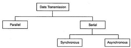
1. Parallel
Transmission
Within a computing or communication
device, the distances between different subunits are too short. Thus, it is
normal practice to transfer data between subunits using a separate wire to
carry each bit of data. There are multiple wires connecting each sub-unit and
data is exchanged using a parallel
transfer mode. This mode of operation results in minimal delays in
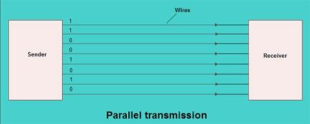
transferring each word. • In parallel transmission, all the bits
of data are transmitted simultaneously on separate communication lines. • In order to transmit n bits, n wires or lines are used. Thus each bit has its own line. • All n bits of one group are
transmitted with each clock pulse from one device to another i.e. multiple bits are sent with
each clock pulse. • Parallel transmission is used for
short distance communication. As shown in the fig, eight separate
wires are used to transmit 8 bit data from sender to receiver. Advantage of parallel
transmission
It is speedy way of transmitting data as
multiple bits are transmitted simultaneously with a single clock pulse. Disadvantage of parallel
transmission
It is costly method of data transmission
as it requires n lines to
transmit n bits at the same
time.
|
|
Unit-02/Lecture-02 |
||||||||||||
2. Serial Transmission (RGPV/
Dec.2012)
When transferring data between two
physically separate devices, especially if the separation is more than a few
kilometers, for reasons of cost, it is more economical to use a single pair
of lines. Data is transmitted as a single bit at a time using a fixed time
interval for each bit. This mode of transmission is known as bit-serial transmission. •
In serial
transmission, the various bits of data are transmitted serially one after the
other. •
It requires only one
communication line rather than n lines
to transmit data from sender to receiver. •
Thus all the bits of
data are transmitted on single line in serial fashion. •
In serial
transmission, only single bit is sent with each clock pulse. •
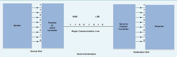
As shown in fig.,
suppose an 8-bit data 11001010 is to be sent from source to destination. Then
least significant bit (LSB) i,e. 0
will be transmitted first followed by other bits. The most significant bit
(MSB) i.e. 1 will be
transmitted in the end via single communication line. •
The internal circuitry
of computer transmits data in parallel fashion. So in order to change this
parallel data into serial data, conversion devices are used. •
These conversion
devices convert the parallel data into serial data at the sender side so that
it can be transmitted over single line. •
On receiver side,
serial data received is again converted to parallel form so that the interval
circuitry of computer can accept it •
Serial
transmission is used for long distance communication. Advantage of Serial
transmission
Use of single
communication line reduces the transmission line cost by the factor of n as compared to parallel
transmission. Disadvantages of Serial
transmission
1. Use of conversion
devices at source and destination end may lead to increase in overall transmission
cost. 2. This method is
slower as compared to parallel transmission as bits are transmitted serially
one after the other. Types of Serial Transmission
•
There
are two types of serial transmission-synchronous and asynchronous both these
transmissions use 'Bit
synchronization' •
Bit Synchronization is a function that
is required to determine when the beginning and end of the data transmission
occurs. •
Bit synchronization helps the
receiving computer to know when data begin and end during a transmission.
Therefore bit synchronization provides timing control. Asynchronous Transmission (RGPV/Dec.2013)
•
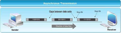
Asynchronous
transmission sends only one character at a time where a character is either a
letter of the alphabet or number or control character i.e. it sends one byte of data at a time. •
Bit
synchronization between two devices is made possible using start bit and stop
bit. •
Start
bit indicates the beginning of data i.e.
alerts the receiver to the arrival of new group of bits. A start bit
usually 0 is added to the beginning of each byte. •
Stop
bit indicates the end of data i.e. to
let the receiver know that byte is finished, one or more additional bits are
appended to the end of the byte. These bits, usually 1s are called stop bits. •
Addition of start and
stop increase the number of data bits. Hence more bandwidth is consumed in
asynchronous transmission. •
There is idle time
between the transmissions of different data bytes. This idle time is also
known as Gap •
The
gap or idle time can be of varying intervals. This mechanism is called
Asynchronous, because at byte level sender and receiver need not to be synchronized.
But within each byte, receiver must be synchronized with the incoming bit
stream. Application of Asynchronous
Transmission
1. Asynchronous
transmission is well suited for keyboard type-terminals and paper tape
devices. The advantage of this method is that it does not require any local
storage at the terminal or the computer as transmission takes place character
by character. 2
Asynchronous
transmission is best suited to Internet traffic in which information is
transmitted in short bursts. This type of transmission is used by modems. Advantages of Asynchronous
transmission
1. This method of data
transmission is cheaper in cost as compared to synchronous e.g. If lines are short,
asynchronous transmission is better, because line cost would be low and idle
time will not be expensive. 2. In this approach
each individual character is complete in itself, therefore if character is
corrupted during transmission, its successor and predecessor character will
not be affected. 3. It is possible to
transmit signals from sources having different bit rates. 4. The transmission
can start as soon as data byte to be transmitted becomes available. 5. Moreover, this mode
of data transmission in easy to implement. Disadvantages of asynchronous
transmission
1. This method is less
efficient and slower than synchronous transmission due to the overhead of
extra bits and insertion of gaps into bit stream. 2. Successful
transmission inevitably depends on the recognition of the start bits. These
bits can be missed or corrupted.
|
|
Unit-02/Lecture-03 |
||||||||
|
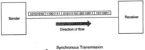
Synchronous Transmission
•
Synchronous
transmission does not use start and stop bits. •
In
this method bit stream is combined into longer frames that may contain
multiple bytes. •
There
is no gap between the various bytes in the data stream. •
In
the absence of start & stop bits, bit synchronization is established
between sender & receiver by 'timing'
the transmission of each bit. •
Since
the various bytes are placed on the link without any gap, it is the
responsibility of receiver to separate the bit stream into bytes so as to
reconstruct the original information. •
In
order to receive the data error free, the receiver and sender operates at the
same clock frequency. Application of Synchronous
transmission
•
Synchronous
transmission is used for high speed communication between computers. Advantage of Synchronous
transmission
1. This method is
faster as compared to asynchronous as there are no extra bits (start bit
& stop bit) and also there is no gap between the individual data bytes. Disadvantages of Synchronous
transmission
1. It is costly as
compared to asynchronous method. It requires local buffer storage at the two
ends of line to assemble blocks and it also requires accurately synchronized
clocks at both ends. This lead to increase in the cost. 2. The sender and
receiver have to operate at the same clock frequency. This requires proper
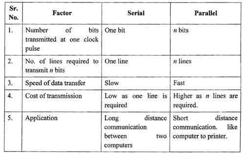
synchronization which makes the system complicated. Comparison between Serial and
Parallel transmission:
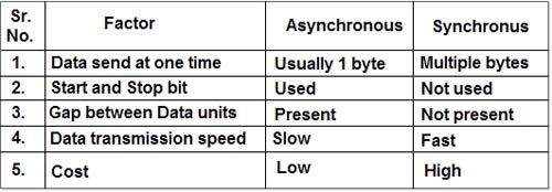
Comparison between Asynchronous
and Synchronous. :
Simplex : ·
Simplex communication
refers to communication that occurs in one direction only. Two definitions
have arisen over time: a common definition, which is used in ANSI standard
and elsewhere, and an
ITU-T definition. Half Duplex : ·
A half-duplex
system provides communication in both directions, but only one direction at a
time (not simultaneously). Typically, once a party begins receiving a signal,
it must wait for the transmitter to stop transmitting, before replying. ·
An example of a half-duplex system
is a two-party system such as a
walkie-talkie,
wherein one must use "Over" or another previously designated
command to indicate the end of transmission, and ensure that only one party
transmits at a time, because both parties transmit and receive on the same
frequency. ·
A good analogy for a half-duplex system would be a
one-lane road with traffic controllers at each end, such as a two-lane bridge
under re-construction. Traffic can flow in both directions, but only one
direction at a time, regulated by the traffic controllers. ·
In automatically run communications systems, such as
two-way data-links, the time allocations for communications in a half-duplex
system can be firmly controlled by the hardware. Thus, there is no waste of
the channel for switching. For example, station A on one end of the data link could be allowed to transmit for exactly
one second, then station B on the other end could
be allowed to transmit for exactly one second, and then the cycle repeats.
|
|
Unit-02/Lecture-04 |
|
Fullduplex : •
A full-duplex system, or sometimes called double-duplex, allows communication
in both directions, and, unlike half-duplex, allows this to happen
simultaneously. Land-line telephone networks are full-duplex, since they allow
both callers to speak and be heard at the same time, with the transition from
four to two wires being achieved by a hybrid coil in a telephone hybrid. •
A good analogy for a full-duplex system would be a
two-lane road with one lane for each direction. In full-duplex mode,
transmitted data does not appear to be sent until it has been actually
received and an acknowledgment was sent back by the other party. •
Two-way radios can be designed as full-duplex systems, transmitting on one frequency and
receiving on another. This is also called frequency-division duplex.
Frequency-division duplex systems can be extended to farther distances using
pairs of simple repeater stations, because the communications transmitted on
any one frequency always travel in the same direction. •
Full-duplex
Ethernet connections work by
making simultaneous use of two physical pairs of twisted cable, where one
pair is used for receiving packets and one pair is used for sending packets
(two pairs per direction for some types of Ethernet), to a directly connected
device. This effectively makes the cable itself a collision-free environment
and doubles the maximum data capacity that can be supported by the
connection. •
There are several benefits to using full-duplex over
half-duplex. Firstly, time is not wasted, since no frames need to be
retransmitted, as there are no collisions. Secondly, the full data capacity
is available in both directions because the send and receive functions are
separated. Thirdly, stations (or nodes) do not have to wait until others
complete their transmission, since there is only one transmitter for each
twisted pair. •
Historically, some computer-based systems of the 1960s and
1970s required full-duplex facilities even for half-duplex operation, because
their poll-and-response schemes could not tolerate the slight delays in
reversing the direction of transmission in a half-duplex line. Unipolar Line Coding •
Unipolar
encoding is a line code. A positive voltage represents a binary 1, and zero volts indicates a binary 0. It
is the simplest line code, directly encoding the bitstream, and is analogous
to on-off keying in modulation. •
Its drawbacks are that it
is not self-clocking and it has a significant DC
component, which can be halved by
using return-to-zero, where the signal returns to zero in the
middle of the bit period. With a 50% duty
cycle each rectangular pulse
is only at a positive voltage for half of the bit period. This is ideal if one symbol is sent much
more often than the other and power considerations are necessary, and also
makes the signal self-clocking. NRZ(Non-Return-Zero)
(RGPV/
Dec 2012) •
Traditionally, a unipolar
scheme was designed as a non-return-to-zero (NRZ) scheme, in which the
positive voltage defines bit 1 and the zero voltage defines bit 0. It
is called NRZ because the signal does not return to zero at the middle of the
bit. •
Compared with its polar
counterpart, Polar NRZ, this scheme is very expensive. The normalized power
(power required to send 1 bit per unit line resistance) is double that for polar
NRZ. For this reason, this scheme is not normally used in data
communications today. Return to zero codes (RGPV/
Dec 2012) •
Return-to-zero (RZ) describes a line
code used in telecommunications signals in which the signal
drops (returns) to zero between each pulse. This takes place even if a number of
consecutive 0s or 1s occur in the signal. The signal is self-clocking. This means that a separate clock does not
need to be sent alongside the signal, but suffers from using twice the
bandwidth to achieve the same data-rate as compared
to non-return-to-zero format. •
The "zero"
between each bit is a neutral or rest condition, such as a zero amplitude in pulse
amplitude modulation (PAM), zero phase
shift in phase-shift
keying (PSK), or mid-frequency in frequency-shift
keying (FSK). That
"zero" condition is typically halfway between the significant
condition representing a 1 bit and
the other significant condition representing a 0 bit. •
Although return-to-zero
(RZ) contains a provision for synchronization, it still has a DC component resulting in “baseline wander” during long
strings of 0 or 1 bits, just like the line code non-return-to-zero. •
Bipolar Line Encoding •
In telecommunication, bipolar encoding is a type of line
code, where two nonzero values are used, so that the three values are +,-,
and zero. Such a signal is called a duobinary
signal. Bipolar encoding typically has at least a rough a balance of
+'s and -'s. •
One kind of bipolar encoding is a paired disparity code. The simplest example of this is alternate mark inversion. In
this code, a binary 0 is encoded as zero volts, as in unipolar encoding, whereas a binary 1 is encoded alternately
as a positive voltage or a negative voltage. The name arose because, in the
context of a T-carrier, a binary '1' is
referred to as a "mark", while a binary '0' is called a
"space". |
|
S.NO |
RGPV
QUESTIONS |
Year |
Marks |
|
Q.1 |
Explain
the RZ and NRZ codes |
DEC2013 Dec 2012 |
4 4 |
|
Unit-02/Lecture-05 |
|||
|
Line Codes (RGPV Dec 2011 / june 2013) •
In base band transmission best way is to map digits or
symbols into pulse waveform. •
This waveform is generally termed as Line codes. •
RZ: Return to Zero [ pulse for half the duration of Tb ] •
NRZ Return to Zero[ pulse for full duration of Tb ] Unipolar NRZ •
“1”
maps to +A pulse “0” maps to no pulse •
Poor
timing •
Low-frequency
content •
Simple •
Long
strings of 1s and 0s ,synchronization problem •
Polar
- (NRZ) •
“1” maps to +A pulse “0” to –A pulse •
Better Average Power •
simple to implement •
Long strings of 1s and 0s ,synchronization problem •
Poor timing Bipolar
Code •
Three signal levels: {-A, 0, +A} •
“1” maps to +A or –A in alternation •
“0” maps to no pulse •
Long string of 0’s causes receiver to loose
synchronization •
Suitable for telephone systems. •
“1”
maps into A/2 first for Tb/2, and -A/2 for next Tb/2 •
“0”
maps into -A/2 first for Tb/2, and A/2 for Tb/2 •
Every
interval has transition in middle –
Timing
recovery easy •
Simple
to implement •
Suitable
for satellite telemetry and optical communications Differential encoding •
t
starts with one initial bit .Assume 0 or 1. •
Signal
transitions are used for encoding. •
Example
NRZ - S and NRZ – M •
NRZ
–S : symbol 1 by no transition , Symbol 0 by transition. •
NRZ-M
: symbol 0 by no transition , Symbol 1 by transition •
Suitable
for Magnetic recording systems. Voltage Build-up •
The
use of a bipolar code prevents a significant build-up of DC,
as the positive and negative pulses average to zero volts. Little or
no DC-component is considered an advantage because the cable may then be used
for longer distances and to carry power for intermediate equipment such as
line repeaters.The DC-component can be easily and cheaply removed before the
signal reaches the decoding circuitry. |
|||
|
S.NO |
RGPV
QUESTIONS |
Year |
Marks |
|
Q.1 |
Explain
the line codes |
June2013 Dec 2011 |
7 7 |
|
UNIT 2/LECTURE 6 |
||||||||||||
Synchronization and Zeroes
1. Bipolar encoding is preferable to non-return-to-zero whenever signal transitions are required
to maintain synchronization between the transmitter and receiver. Other
systems must synchronize using some form of out-of-band communication, or add
frame
synchronization sequences that don't
carry data to the signal. These alternative approaches require either an
additional transmission medium for the clock signal or a loss of performance
due to overhead, respectively. A bipolar encoding is an often good
compromise: runs of ones will not cause a lack of transitions. 2. However, long sequences of zeroes remain an
issue. Long sequences of zero bits result in no
transitions and a loss of synchronization. Where frequent transitions
are a requirement, a self-clocking encoding such as return-to-zero or some other more complicated line
code may be more appropriate,
though they introduce significant overhead. 3. The coding was used extensively in
first-generation PCM networks, and is still commonly seen on older
multiplexing equipment today, but successful
transmission relies on no long runs of zeroes being present. No more than 15
consecutive zeros should ever be sent to ensure synchronization. 4. There are two popular ways to ensure that
no more than 15 consecutive zeros are ever sent: robbed-bit
signaling and bit
stuffing. 5. T-carrier uses robbed-bit signaling: the
least-significant bit of the byte is simply forced to a "1" when
necessary. 6. The modification of bit 7 causes a change
to voice that is undetectable by the human ear, but it is an unacceptable
corruption of a data stream. Data channels are
required to use some other form of pulse-stuffing,such as always setting bit
8 to '1', in order to maintain a sufficient density of ones. 7. If the characteristics
of the input data do not follow the pattern that every eighth bit is '1', the
coder using alternate mark inversion adds a '1' after seven consecutive zeros
to maintain synchronisation. On the decoder side, this extra '1' added by the
coder is removed, recreating the correct data. Using this method the data
sent between the coder and the decoder is longer than the original data by
less than 1% on average. Of course, this lowers the effective data throughput
to 56 kbit/s per channel. Error detection
•
Another benefit of
bipolar encoding compared to unipolar is error detection. In the T-carrier example, the bipolar
signals are regenerated at regular intervals so that signals diminished by
distance are not just amplified, but detected and recreated anew. Weakened
signals corrupted by noise
could cause errors, a mark interpreted as zero, or zero as positive or
negative mark. Every single-bit error results in a violation of the bipolar
rule. Each such bipolar
violation (BPV) is an indication
of a transmission error. Baud •
Baud is synonymous to symbols per second or pulses per second. It is the unit
of symbol rate, also known as baud or modulation
rate; the number of distinct symbol changes (signaling events) made to the transmission medium per second in a digitally modulated signal or a line code. Baud is related to but should not be
confused with gross bit rate expressed as bits per second, bps, b/s,
bit/s or bits/s. However, though technically incorrect, in the case of modem
manufacturers baud commonly refers to bits per second. They make a
distinction by also using the term characters per second (CPS). In these
anomalous cases, refer to the modem manufacturer's documentation to ensure an
understanding of their use of the term "baud". •
The symbol duration time, also known as unit interval, can be directly measured as the time
between transitions by looking into an eye diagram of an oscilloscope. The symbol duration time Ts can be calculated as: •
•
where fs
is the symbol rate. There is also a chance of miscommunication which leads to
ambiguity. •
example: A baud of 1 kBd = 1,000
Bd is synonymous to a symbol rate of 1,000 symbols per second. In case of a modem, this corresponds to
1,000 tones per second, and in case of a line code, this corresponds to 1,000
pulses per second. The symbol duration time is 1/1,000 second = 1
millisecond. •
In digital systems (i.e., using
discrete/discontinuous values) with binary code, 1 Bd = 1 bit/s. By contrast, non-digital
(or analog) systems use a continuous range of values
to represent information and in these systems the exact informational size of
1 Bd varies. Modem
(RGPV/ Dec 2012) Modem, ·
moden short for modulator-demodulator
is an electronic device that converts a computer’s digital
signals into specific frequencies to travel over telephone or cable
television lines. At the destination, the receiving modem demodulates the
frequencies back into digital data. Computers use modems to communicate with
one another over a network. The modem has significantly evolved since the
1970s when the 300 baud modem was
used for connecting computers to bulletin board systems (BBSs). With this
type of modem, each bit, represented digitally by a 1 or 0, was transmitted
as a specific tone. The receiving modem responded with
its own dedicated frequencies so that the modems could “talk at the same time.” ·
The technical term for this
type of modem is Asynchronous. ·
Image of modem: Types
of modem: External modem: 1. External modems. 2.
Usb modem 3. Cable
modem: 4.
Wireless
modem 5.
Gprs modem 6.
High
speed modem 7.
Null
modem
|
|
UNIT
2/LECTURE 7 |
||||||||||||||||||||||||||||||||||
|
Types of modem: External modem 1.
External
modems.
It is the second term we have to consider from different types of computer
modem. An External modem can be used to
the same purpose and in the same conditions as internal computer modem.
However, external modem is a small box that uses other kind of interfaces to
be connected to the computer. 2.
Usb modem: It could be a serial
modem, named thus because it uses the serial port to connect to the computer.
Usually installed on the back of the computer, the serial port is an
easy-to-install option for the external modem. The same small box, on the
other hand, can be an USB modem, which normally uses USB
port usually placed on the back or in front of the computer. 3. Cable
modem: The cable modem uses a coaxial cable
television lines to provide greater bandwidth than the dial-up computer
modem. An extremely fast access to the Web is providing by the cable modem
with downstream transmission up to 38 Mbits/s and an upstream transmission up
to 1 Mbits/s. 4.
Wireless
modem: Some Internet Service Providers
supports wireless internet services. The wireless
modems are used for this service. These modems work similar to traditional
wired modems except its structure. 5.
Gprs modem: The
GPRS modems are used to browser internet and for other communication using
the GPRS services. The GPRS (General Packet Radio Signals) service is
provided on the cellular networks. If we have cellular connection then we can
communicate using the GPRS modems. The GPRS services are costly as compared
with other communication services. 6.
High
speed modem: 56k modems are designed to
take advantage of the new digital telephone
networks. These use Pulse Code Modulation (PCM) to convert
your voice, fax or modem signal into a digital stream at your
local exchange. The amplitude of the analog signal is measured
8000 times per second. Each measurement produces a PCM code in the form of an
eight bit byte to represent the amplitude. 7.
Null
modem: Null modem is a communication
method to connect two DTEs (computer, terminal, printer etc.) directly
using an RS-232serial cable. The
RS-232 standard is asymmetrical as to the definitions of the two ends of the
communications link so it assumes that one end is a DTE and the other is a DCE e.g.
a modem. With a null modem
connection, the transmit and
receive lines are crosslinked. Depending on the purpose,
sometimes also one or more handshake lines are
crosslinked. Several wiring layouts are in use because the null modem
connection is not covered by a standard Advantages: 1.
More useful in connecting LAN
with the Internet 2.
Speed depends on the cost Disadvantages: 1.
Acts just as a interface
between LAN and Internet 2.
No traffic maintenance is present
Point to multipoint configuration (RGPV/ Dec 2012) Point to Multi-Point Network Diagram
Description:
•
Point to multi-point
networks are used to connect one location to one or more remote locations.
The above diagram shows three connected multi-user networks (using a Hub or
Switch). Any location may be configured as a Direct connection (without a Hub or Switch). •
Air-Frame 100 at location
B can be used to create many, co-located point to multi-point networks or cells. •
Applications:
•
Internet, Intranet or Extranet configurations. ISP access networks. LAN to LAN
applications (bridged or routed see below). Remote data capture (Telemetry or
SCADA). Remote Control. Remote Monitoring, Security, Hub and Spoke,
Conferencing. Bridged
or Routed:
•
In a bridged connection (Air-Frame 10 or 100 range) the network traffic is sent
from one location to all other locations and consists of: •
Traffic for a PC or
system on any other network i.e. traffic from location A to, say, a system at
location B, is also received by Location C (but is only sent once over the
radio) and is placed on the local LAN at C by the
bridging function. •
In effect all the locations operate as a
single, fully transparent LAN. Where one or more locations consist of many
PCs or systems the broadcast traffic alone can be considerable and
consideration should be given to using a routed network. In addition the
redundant traffic •
received at each location
can stress the local LAN network and cause security concerns. In this case
also a routed solution should be considered. •
In a routed connection
(Air-Frame 100 range) the traffic is sent from one location to all other
Locations consists and consists only of: •
Traffic for a PC or
system on any other network i.e. traffic from location A to, say, a system at
location B, is also received by Location
C (but is only sent once). The routing function however prevents this redundant traffic from being placed on the local LAN at
C. •
In this configuration the
LANs operate independently but communication is enabled between them.
|