|
UNIT
– 4 |
||||||||
|
Switching Techniques |
||||||||
|
Unit-04/Lecture-01 |
||||||||
|
Switching Techniques
Switching
is a technique which is used in large network,large I mean those networks
that contains large no. of node,wire,device etc.In this type of networks it
is difficult to connect nodes point to point.So in this situation we used
Switching Technique.In simple words Switching is a hardware or software
device which create a connection between one or more than one
device/node/computer. Packet Switching Packet switching features delivery of variable bitrate data streams (sequences of packets) over a
shared network which allocates transmission resources as needed using statistical
multiplexing or dynamic bandwidth allocation techniques. When traversing network adapters, switches, routers, and other network
nodes, packets are buffered
and queued, resulting in variable delay and throughput depending on the network's capacity and
the traffic load on the network. Packet switching
contrasts with another principal networking paradigm, circuit
switching, a method which sets up
a limited number of dedicated connections of constant bit rate and constant
delay between nodes for exclusive use during the
communication session. In cases where traffic fees are charged (as
opposed to flat rate), for example in cellular
communication services, circuit
switching is characterized by a fee per unit of connection time, even when no
data is transferred, while packet switching is characterized by a fee per
unit of information transmitted (characters, packets, messages) Packet mode communication may be utilized with or
without intermediate forwarding nodes (packet switches or routers). Packets are normally forwarded by
intermediate network nodes asynchronously using first-in, first-out buffering, but may be forwarded according
to some scheduling discipline for fair queuing, traffic shaping, or for differentiated or guaranteed quality
of service, such as weighted
fair queuing or leaky
bucket. In case of a shared
physical medium (radio, 10BASE5 or thick Ethernet,), the packets may be delivered according
to a multiple access scheme. Packet switching features delivery of variable bitrate data streams (sequences of packets) over a
shared network which allocates transmission resources as needed using statistical
multiplexing or dynamic bandwidth allocation techniques. When traversing network adapters, switches, routers, and other network
nodes, packets are buffered
and queued, resulting in variable delay and throughput depending on the network's capacity and
the traffic load on the network. Packet switching
contrasts with another principal networking paradigm, circuit
switching, a method which sets up
a limited number of dedicated connections of constant bit rate and constant
delay between nodes for exclusive use during the
communication session. In cases where
traffic fees are charged (as opposed to flat rate), for example in cellular
communication services, circuit
switching is characterized by a fee per unit of connection time, even when no
data is transferred, while packet switching is characterized by a fee per
unit of information transmitted (characters, packets, messages. Circuit
Switching Circuit
switching is a methodology of implementing a telecommunications
network in which two network
nodes establish a dedicated communications
channel (circuit) through the network before the nodes may
communicate. The circuit guarantees the full bandwidth of the channel and
remains connected for the duration of the communication session. The circuit
functions as if the nodes were physically connected as with an electrical
circuit. The defining example of a
circuit-switched network is the early analog telephone
network. When a call is made from one telephone to another,
switches within the telephone
exchanges create a continuous wire
circuit between the two telephones, for as long as the call lasts. Circuit switching
contrasts with packet switching which divides the data to be transmitted
into packets transmitted through the network
independently. In packet switching, instead of being dedicated to one
communication session at a time, network links are shared by packets from
multiple competing communication sessions, resulting in the loss of the
quality of service guarantees that are provided by circuit switching. In circuit switching, the
bit delay is constant during a connection, as opposed to packet switching,
where packet queues may cause varying and potentially indefinitely long packet
transfer delays. No circuit can be degraded
by competing users because it is protected from use by other callers until
the circuit is released and a new connection is set up. Even if no actual
communication is taking place, the channel remains reserved and protected
from competing users. Virtual
circuit switching is a packet switching technology that emulates circuit
switching, in the sense that the connection is established before any packets
are transferred, and packets are delivered in order. While circuit switching
is commonly used for connecting voice circuits, the concept of a dedicated
path persisting between two communicating parties or nodes can be extended to
signal content other than voice. Its advantage is that it provides for
continuous transfer without the overhead associated with packets making maximal use of available bandwidth
for that communication. Its disadvantage is that it can be relatively
inefficient because unused capacity guaranteed to a connection cannot be used
by other connections on the same network. Hybrid
Switching (RGPV Dec2012) Our new-generation Hybrid Switch
Technology represents a major evolution. With full bandwidth for SDH and
packet connections, it offers traffic switching in native formats and the
deployment flexibility of non-blocking connectivity, using patent-pending
technology. The new technology provides a
bandwidth of 480Gb/s for both TDM circuits and packet connections, with the
native-format traffic switching including native SDH cross-connecting, free
of circuit emulation penalties for TDM switching. Similarly, native packet
switching is achieved without any stranded bandwidth. Non-blocking connectivity enables
every input to connect to any output, while offering native multicast
broadcast functionality, with Fujitsu’s technology reducing the overall
complexity of the system and increasing its throughput. Single Bit Error
And Burst Error When data is being
transmitted from one machine to another, it may be possible that data become
corrupted on its, way. Some of the bits may be altered, damaged or lost
during transmission. Such a condition is known as error. The error may occur because of noise on
line, attenuation and delay distortion. For reliable communication, it is
important that errors are detected and corrected.
|
|
Unit-04/Lecture-02 |
||||||||
Type of Errors (RGPV Dec2013)
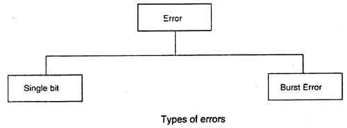
There are two main types of errors in
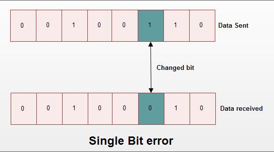
transmissions: 1 single bit error 2 burst error Single bit error: It means only one bit of data unit is
changed from 1 to 0 or from 0 to 1 as shown in fig. Single bit error can happen in parallel transmission
where all the data bits are transmitted using separate wires. Single bit errors are the least likely type of error in
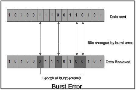
serial transmission. Burst Error: It means two or more bits in data unit
are changed from 1 to 0 from 0 to 1 as shown in fig. In burst error,
it is not necessary that only consecutive bits are changed. The length of
burst error is measured from first changed bit to last changed bit. As shown
in fig. length of burst error is 8, although some bits are unchanged in
between. Burst error is most likely to occur in a serial transmission. The
noise occurring for a longer duration affects multiple bits. The number of bits
affected depends on the data rate & duration of noise. For e.g. if data rate is 1 kbps, a
noise of 1/100 second can affect 10 bits. Error Detection Schemes
Error detection is most commonly
realized using a suitable hash function (or checksum algorithm). A hash function adds a
fixed-length tag to a
message, which enables receivers to verify the delivered message by
recomputing the tag and comparing it with the one provided. There exists a vast
variety of different hash function designs. However, some are of particularly
widespread use because of either their simplicity or their suitability for
detecting certain kinds of errors (e.g., the cyclic
redundancy check's performance in
detecting burst errors). Random-error-correcting
codes based on minimum
distance coding can provide a
suitable alternative to hash functions when a strict guarantee on the minimum
number of errors to be detected is desired. Repetition codes, described
below, are special cases of error-correcting codes: although rather
inefficient, they find applications for both error correction and detection
due to their simplicity.
|
|
Unit-04/Lecture-03 |
||||||||
|
Repetition Codes
A repetition code is a coding scheme that repeats the bits
across a channel to achieve error-free communication. Given a stream of data
to be transmitted, the data is divided into blocks of bits. Each block is
transmitted some predetermined number of times. For example, to send the bit
pattern "1011", the four-bit block can be repeated three times,
thus producing "1011 1011 1011". However, if this twelve-bit
pattern was received as "1010 1011 1011" – where the first block is
unlike the other two – it can be determined that an error has occurred. Repetition codes are very
inefficient, and can be susceptible to problems if the error occurs in
exactly the same place for each group (e.g., "1010 1010 1010" in
the previous example would be detected as correct). The advantage of
repetition codes is that they are extremely simple, and are in fact used in
some transmissions of numbers stations. Parity Bits
A parity bit is a bit that is added to a group of source bits to
ensure that the number of set bits (i.e., bits with value 1) in the outcome
is even or odd. It is a very simple scheme that can be used to detect single
or any other odd number (i.e., three, five, etc.) of errors in the output. An
even number of flipped bits will make the parity bit appear correct even
though the data is erroneous. Extensions and variations
on the parity bit mechanism are horizontal
redundancy checks, vertical
redundancy checks, and "double,"
"dual," or "diagonal" parity (used in RAID-DP). Checksums
A checksum of a message is a modular
arithmetic sum of message code
words of a fixed word length (e.g., byte values). The sum may be negated by
means of a ones'-complement operation prior to transmission to detect
errors resulting in all-zero messages. Checksum schemes include parity
bits, check
digits, and longitudinal redundancy checks. Some checksum schemes, such as the Damm
algorithm, the Luhn
algorithm, and the Verhoeff
algorithm, are specifically
designed to detect errors commonly introduced by humans in writing down or
remembering identification numbers. Cyclic Redundancy Checks (Crcs) (RGPV Dec2013)
A cyclic redundancy check (CRC) is a
single-burst-error-detecting cyclic code and non-secure hash
function designed to detect
accidental changes to digital data in computer networks. It is not suitable
for detecting maliciously introduced errors. It is characterized by
specification of a so-called generator
polynomial, which is used as the divisor in a polynomial
long division over a finite
field, taking the input data
as the dividend, and where the remainder becomes the result. Cyclic codes have
favorable properties in that they are well suited for detecting burst
errors. CRCs are particularly
easy to implement in hardware, and are therefore commonly used in digital networks and storage devices such as hard disk drives. Even parity is a special
case of a cyclic redundancy check, where the single-bit CRC is generated by
the divisor x + 1. Cryptographic Hash Functions
The output of a cryptographic hash function, also
known as a message digest,
can provide strong assurances about data integrity, whether changes of the data are
accidental (e.g., due to transmission errors) or maliciously introduced. Any
modification to the data will likely be detected through a mismatching hash
value. Furthermore, given some hash value, it is infeasible to find some
input data (other than the one given) that will yield the same hash value. If
an attacker can change not only the message but also the hash value, then a keyed hash or message
authentication code (MAC) can be used for
additional security. Without knowing the key, it is infeasible for the
attacker to calculate the correct keyed hash value for a modified message. Error-Correcting Codes
Any error-correcting code
can be used for error detection. A code with minimum Hamming
distance, d, can detect up to d
− 1 errors in a code word. Using minimum-distance-based
error-correcting codes for error detection can be suitable if a strict limit
on the minimum number of errors to be detected is desired. Codes with minimum
Hamming distance d = 2 are
degenerate cases of error-correcting codes, and can be used to detect single
errors. The parity bit is an example of a single-error-detecting
code. Error Correction
Automatic Repeat Request
Automatic
Repeat reQuest (ARQ) is an error
control method for data transmission that makes use of error-detection codes,
acknowledgment and/or negative acknowledgment messages, and timeouts to achieve reliable data transmission. An acknowledgment is a message sent by
the receiver to indicate that it has correctly received a data
frame. Usually, when the
transmitter does not receive the acknowledgment before the timeout occurs
(i.e., within a reasonable amount of time after sending the data frame), it
retransmits the frame until it is either correctly received or the error
persists beyond a predetermined number of retransmissions. Three types of ARQ
protocols are Stop-and-wait
ARQ, Go-Back-N
ARQ, and Selective
Repeat ARQ. ARQ is appropriate if the
communication channel has varying or unknown capacity, such as is the case on the Internet.
However, ARQ requires the availability of a back
channel, results in possibly
increased latency due to retransmissions, and requires the
maintenance of buffers and timers for retransmissions, which in the case of network
congestion can put a strain on the
server and overall network capacity. Error-correcting code
An error-correcting
code (ECC) or forward error
correction (FEC) code is a system of adding redundant data, or parity data, to a message, such that it can be recovered by a
receiver even when a number of errors (up to the capability of the code being
used) were introduced, either during the process of transmission, or on
storage. Since the receiver does not have to ask the sender for
retransmission of the data, a back-channel is not required in forward error
correction, and it is therefore suitable for simplex
communication such as broadcasting. Error-correcting codes are frequently
used in lower-layer communication, as well as for reliable
storage in media such as CDs, DVDs, hard disks, and RAM. Error-correcting codes
are usually distinguished between convolutional
codes and block
codes:
Shannon's
theorem is an important theorem
in forward error correction, and describes the maximum information rate at which reliable communication is
possible over a channel that has a certain error probability or signal-to-noise
ratio (SNR). This strict upper
limit is expressed in terms of the channel capacity. More specifically, the theorem says that
there exist codes such that with increasing encoding length the probability
of error on a discrete memoryless channel can be made arbitrarily small, provided
that the code rate is smaller than the channel capacity. The
code rate is defined as the fraction k/n
of k source symbols and n encoded symbols. The actual maximum code
rate allowed depends on the error-correcting code used, and may be lower.
This is because Shannon's proof was only of existential nature, and did not
show how to construct codes which are both optimal and have efficient encoding and decoding algorithms.
|
|
Unit-04/Lecture-04 |
|
Integrated Services for Digital Network (ISDN) (RGPV
Dec2012/Dec 2013) Integrated
Services for Digital Network (ISDN) is a set of communication standards for simultaneous digital transmission of voice, video, data, and other network
services over the traditional circuits of the public switched telephone network. It was first defined in 1988 in the CCITT red book. Prior to ISDN, the telephone
system was viewed as a way to transport voice, with some special services
available for data. The key feature of ISDN is that
it integrates speech and data on the same lines, adding features that were
not available in the classic
telephone system. There are several kinds
of access interfaces to ISDN defined as Basic
Rate Interface (BRI), Primary
Rate Interface (PRI), Narrowband ISDN (N-ISDN), and Broadband
ISDN (B-ISDN). ISDN is a circuit-switched telephone
network system, which also
provides access to packet
switched networks, designed to allow
digital transmission of voice and data over ordinary telephone
copper wires, resulting in
potentially better voice quality than an analog phone can provide. It offers
circuit-switched connections (for either voice or data), and packet-switched
connections (for data), in increments of 64 kilobit/s. A major market application for ISDN in
some countries is Internet access, where ISDN typically provides a maximum
of 128 kbit/s in both upstream and downstream directions. Channel bonding can achieve a greater data rate; typically
the ISDN B-channels of three or four BRIs (six to
eight 64 kbit/s channels) are bonded. ISDN should not be
mistaken for its use with a specific protocol, such as Q.931 where as ISDN is employed as the network,
data-link and physical layers in the context of the OSI
model. In a
broad sense ISDN can be considered a suite of digital services
existing on layers 1, 2, and 3 of the OSI model. ISDN is designed to provide
access to voice and data services simultaneously. However, common use
reduced ISDN to be limited to Q.931 and related protocols, which are a set of
protocols for establishing and breaking circuit
switched connections, and for advanced calling features for the user. They were introduced in
1986. In a videoconference, ISDN provides simultaneous voice, video,
and text transmission between individual desktop videoconferencing systems
and group (room) videoconferencing systems ISDN Interface
The entry level interface
to ISDN is the Basic(s) Rate Interface (BRI), a 128 kbit/s service delivered over a pair of standard
telephone copper wires. The 144 kbit/s payload rate is broken down into two
64 kbit/s bearer channels ('B' channels) and one 16 kbit/s signaling
channel ('D' channel or data channel). This is
sometimes referred to as 2B+D. The interface specifies
the following network interfaces:
Primary Rate Interface
The other ISDN access available is the Primary
Rate Interface (PRI), which is carried over an E1 (2048 kbit/s) in most parts of the world.
An E1 is 30 'B' channels of 64 kbit/s, one 'D' channel of 64 kbit/s and a
timing and alarm channel of 64 kbit/s. In North America PRI
service is delivered on one or more T1 carriers (often referred to as 23B+D) of 1544
kbit/s (24 channels). A PRI has 23 'B' channels and 1 'D' channel for
signalling (Japan uses a circuit called a J1, which is similar to a T1).
Inter-changeably but incorrectly, a PRI is referred to as T1 because it uses
the T1 carrier format. A true T1 (commonly called "Analog T1" to
avoid confusion) uses 24 channels of 64 kbit/s of in-band
signaling. Each channel uses 56 kb
for data and voice and 8 kb for signaling and messaging. PRI uses out of band
signaling which provides the 23 B channels with clear 64 kb for voice and
data and one 64 kb 'D' channel for signaling and messaging. In North America,
Non-Facility Associated Signalling allows two or more PRIs to be controlled
by a single D channel, and is sometimes called "23B+D +
n*24B". D-channel backup allows for a second D channel in case the
primary fails. NFAS is commonly used on a T3. PRI-ISDN is popular
throughout the world, especially for connecting PBXs to PSTN. While the North American
PSTN can use PRI or Analog T1 format from PBX to PBX, the POTS or BRI can be delivered to a business or
residence. North American PSTN can connect from PBX to PBX via Analog T1, T3,
PRI, OC3, etc. Even though many network professionals use the term
"ISDN" to refer to the lower-bandwidth BRI circuit, in North
America BRI is relatively uncommon whilst PRI circuits serving PBXs are
commonplace. ISDN Devices
ISDN devices include terminals, terminal adapters (TAs),
network-termination devices, line-termination equipment, and
exchange-termination equipment. ISDN terminals come
in two types. Specialized ISDN terminals are referred to as terminal
equipment type 1 (TE1). Non-ISDN terminals, such as DTE, that predate the ISDN standards are referred to as terminal equipment
type 2 (TE2). TE1s connect to the ISDN network through a four-wire, twisted-pair
digital link. TE2s connect to the ISDN network through a TA. The ISDN TA can
be either a standalone device or a board inside the TE2. If the TE2 is
implemented as a standalone device, it connects to the TA via a standard
physical-layer interface. Examples include EIA/TIA-232-C (formerly RS-232-C),
V.24, and V.35. Beyond the TE1 and TE2 devices, the next connection point
in the ISDN network is the network termination type
1 (NT1) or network termination type 2 (NT2) device. These are
network-termination devices that connect the four-wire subscriber wiring to
the conventional two-wire local loop. In North America, the NT1 is a customer
premises equipment (CPE) device. In most other parts of the world, the NT1 is
part of the network provided by the carrier. The NT2
is a more complicated device that typically is found in digital private
branch exchanges (PBXs) and that performs Layer 2 and 3 protocol functions
and concentration services. An NT1/2 device also exists as a single device
that combines the functions of an NT1 and an NT2. ISDN specifies a number of reference points that define
logical interfaces between functional groups, such as TAs and NT1s. ISDN
reference points include the following:
Figure: Sample ISDN Configuration Illustrates Relationships Between
Devices and Reference Points
|
|
S.NO |
RGPV
QUESTIONS |
Year |
Marks |
|
Q.1 |
What
is ISDN.Discuss ISDN services and ISDN protocols |
DEC2013 Dec 2012 |
7 7 |
|
Unit-04/Lecture-05 |
Services (RGPV Dec2013)
There are two types of services associated with ISDN:
ISDN BRI Service
The ISDN Basic Rate Interface (BRI) service offers two B
channels and one D channel (2B+D). BRI B-channel service operates at 64 kbps
and is meant to carry user data; BRI D-channel service operates at 16 kbps
and is meant to carry control and signaling information, although it can
support user data transmission under certain circumstances. The D channel
signaling protocol comprises Layers 1 through 3 of the OSI reference model.
BRI also provides for framing control and other overhead, bringing its total
bit rate to 192 kbps. The BRI physical layer specification is International
Telecommunication Union-Telecommunications Standards Section (ITU-T)
(formerly the Consultative Committee for International
Telegraph and Telephone [CCITT]) I.430. ISDN PRI Service
ISDN Primary Rate Interface (PRI) service offers 23 B
channels and 1 D channel in North America and Japan, yielding a total bit
rate of 1.544 Mbps (the PRI D channel runs at 64
kbps). ISDN PRI in Europe, Australia, and other parts of the world provides
30 B channels plus one 64-kbps D channel and a total interface rate of 2.048
Mbps. The PRI physical layer specification is ITU-T I.431. ISDN Specifications
This section describes the various ISDN specifications for
Layer 1, Layer 2, and Layer 3. Layer 1
ISDN physical layer
(Layer 1) frame formats differ depending on whether the frame is outbound
(from terminal to network) or inbound (from network to terminal). Both
physical layer interfaces are shown in Figure: ISDN Physical Layer Frame
Formats Differ Depending on Their Direction. The frames are 48 bits long, of which 36 bits represent
data. The bits of an ISDN physical layer frame are used as follows:
Figure: ISDN Physical Layer Frame Formats Differ Depending on Their
Direction Multiple ISDN user devices can be physically attached to
one circuit. In this configuration, collisions can result if two terminals
transmit simultaneously. Therefore, ISDN provides features to determine link
contention. When an NT receives a D bit from the TE, it echoes back the bit
in the next E-bit position. The TE expects the next E bit to be the same as
its last transmitted D bit. Terminals cannot transmit into the D
channel unless they first detect a specific number of ones (indicating
"no signal") corresponding to a pre-established priority. If the TE
detects a bit in the echo (E) channel that is different from its D bits, it
must stop transmitting immediately. This simple technique ensures that only
one terminal can transmit its D message at one time. After successful
D-message transmission, the terminal has its priority reduced by requiring it
to detect more continuous ones before transmitting. Terminals cannot raise
their priority until all other devices on the same line have had an
opportunity to send a D message. Telephone connections have higher priority
than all other services, and signaling information has a higher priority than
nonsignaling information. Layer 2
Layer 2 of the ISDN
signaling protocol is Link Access Procedure, D channel (LAPD). LAPD is
similar to High-Level Data Link Control (HDLC) and Link Access Procedure,
Balanced (LAPB). As the expansion of the LAPD acronym indicates, this layer
is used across the D channel to ensure that control and signaling information
flows and is received properly. The LAPD frame format (see Figure: LAPD Frame Format Is
Similar to That of HDLC and LAPB)is very similar to that of HDLC; like HDLC, LAPD uses supervisory,
information, and unnumbered frames. The LAPD protocol is formally specified
in ITU-T Q.920 and ITU-T Q.921. Figure: LAPD Frame Format Is Similar to That of HDLC and LAPB
The LAPD Flag and Control fields are identical to those of
HDLC. The LAPD Address field can be either 1 or 2 bytes long. If the extended
address bit of the first byte is set, the address is 1 byte; if it is not
set, the address is 2 bytes. The first Address-field byte contains the
service access point identifier (SAPI), which identifies the portal at which
LAPD services are provided to Layer 3. The C/R bit indicates whether the
frame contains a command or a response. The Terminal Endpoint Identifier
(TEI) field identifies either a single terminal or multiple terminals. A TEI
of all ones indicates a broadcast. |
|
S.NO |
RGPV
QUESTIONS |
Year |
Marks |
|
Q.1 |
What
is ISDN. Discuss ISDN services |
Dec
2013 |
7 |
|
UNIT 4/LECTURE 6 |
||||||||
Layer 3
Two Layer 3 specifications are used for ISDN signaling:
ITU-T (formerly CCITT) I.450 (also known as ITU-T Q.930) and ITU-T I.451
(also known as ITU-T Q.931). Together, these protocols support user-to-user,
circuit-switched, and packet-switched connections. A variety of
call-establishment, call-termination, information, and miscellaneous messages
are specified, including SETUP, CONNECT, RELEASE, USER INFORMATION, CANCEL,
STATUS, and DISCONNECT. These messages are functionally similar to those
provided by the X.25 protocol. Figure: An ISDN Circuit-Switched
Call Moves Through Various Stages to Its Destination, from ITU-T I.451, shows the typical
stages of an ISDN circuit-switched call. Figure: An ISDN Circuit-Switched Call Moves Through Various Stages to
Its Destination
ISDN is comprised of digital telephony and data-transport
services offered by regional telephone carriers. ISDN involves the
digitization of the telephone network to transmit voice, data, text,
graphics, music, video, and other source material over existing telephone
wires. ISDN devices include the following:
The ISDN specification references specific connection
points that define logical interfaces between devices. ISDN uses the following two types of services:
ISDN runs on the bottom three layers of the OSI reference
model, and each layer uses a different specification to transmit data. •
Terminal Adapter (TA) -
Converter device that converts standard electrical signals into the form used
by ISDN - allows non-ISDN devices to operate on an ISDN network.
•
Terminal Equipment Type 1 (TE1)
- Compatible with the ISDN network.
Example:Telephones, personal computers, fax machine or
videoconferencing machine.
•
Terminal Equipment Type 2 (TE2)
- Not compatible with the ISDN network. Example: Analog phone or modem,
requires a TA (TE2 connects to TA).
•
Network termination type 1
& 2 (NT1 and NT2) - A small
connection box that physically connects the customer site to the telco local
loop, provides a four-wire connection to the customer site and a two-wire
connection to the network (PRI – CSU/DSU).
Protocols
Specifications defining
the physical layer and part of the data link layers of
ISDN: From the point of view of
the OSI architecture, an ISDN
line has a stack of three protocols
ISDN services (RGPV
Dec2013) •
Basic
Rate Interface (BRI) –
Two 64 Kbps B channels,
one 16 Kbps D channel, and 48 Kbps worth of framing and synchronization. –
Available
data bandwidth: 128 Kbps (2 x 64 Kbps) –
User
bandwidth: 144 Kbps (128 Kbps + a 16 Kbps D channel) –
Total
line capacity: 192 Kbps (144 Kbps + 48
Kbps framing) •
Each
B channel can be used for separate applications –
Such
as Internet and Voice •
Allows individual B channels to
be aggregated together into a Multilink channel •
Primary Rate Interface (PRI) –
A PRI connection can assign various 64 Kbps channels to
both ISDN and analog modem connections –
North America and Japan – PRI service has 23 64 Kbps B
channels, one 64 Kbps D channel, and 8 Kbps of synchronization and framing
for a total bit rate of up to 1.544 Mbps (same as T1) –
Europe, Australia, and other parts of the world – PRI
service has 30 64 Kbps B channels, one 64 Kbps D channel, and 64 Kbps of
framing and synchronization for a total bit rate of up to 2.048 Mbps (same as
E1) •
Each B channel to be used for
separate applications including voice, data and Internet •
Multiple B channels can be
Multilinked together
|
|
UNIT 4/LECTURE 7 |
|
ISDN
refrence points •
U - Two wire cable that connects the customer’s equipment
to the telecommunications provider •
R - Point between non-ISDN equipment (TE2) and the TA •
S - Four-wire cable from TE1 or TA to the NT1 or NT2 •
T - Point between NT1 and NT2 •
The ISDN Physical Layer •
The ISDN Data Link Layer •
The ISDN Network Layer Physical layer ISDN protocols –
BRI (ITU-T I.430) / PRI (ITU-T I.431) •
Defines two ISDN physical layer frame formats –
Inbound (local exchange to ISDN customer) –
Outbound (ISDN customer to local exchange ) •
Data link layer ISDN protocols –
LAPD signaling protocol (ITU-T Q.920 for BRI and Q.921 for
PRI) for transmitting control and signaling information over the D channel •
LAPD frame format similar to ISO HDLC frame format •
Network layer ISDN protocols –
ITU-T I.930 and ITU-T Q.931 defines switching and
signaling methods using the D channel.
|